
Campus Floor Connectivity Design
Enterprise building-to-building campus design using FortiGate 600-series firewalls in HA, Cisco C9300 StackWise, Cisco C9500 StackWise Virtual, OM3 multimode fiber, access zones, segmentation, and clear operational handoff.
On This Design
Design Context
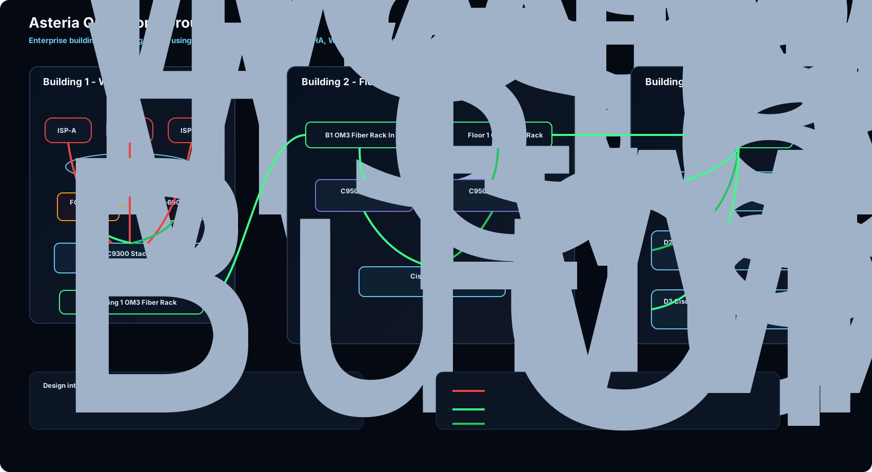
The scenario was a building-to-building campus connectivity design. Building 1 handled the WAN handoff: ISP service links land on the Cisco C9300 StackWise block, the SD-WAN zone connects into the FortiGate 600-series HA firewall pair, and the C9300 feeds the Building 1 OM3 fiber rack. Building 2 hosted the campus core on Floor 1 using two Cisco C9500 switches in StackWise Virtual, with an OM3 fiber rack extending toward Floor 5 access zones and a local Floor 1 extension area.
I remember putting a lot of care into this design because it was not just about "connecting switches." The real work was defining the physical fiber path, the security handoff, the campus core role, the Floor 5 access distribution model, and the operational documentation that would make troubleshooting easier later.
Hardware Inventory and Roles
This section is only the logical role view. It maps each layer to its platform and operational responsibility without trying to behave like a procurement list or a cable schedule. The goal is to make the architecture readable before getting into exact part numbers.
| Layer / Role | Recommended Platform | Quantity | Purpose | Reference |
|---|---|---|---|---|
| Building 1 SD-WAN Zone | FortiGate 600-series HA pair | 2 firewalls | Firewall policy, SD-WAN services, Internet security boundary, and controlled routing into the campus. | FortiGate 600F |
| Building 1 WAN Aggregation | Cisco Catalyst C9300 StackWise | Stacked switch block | Receives ISP/WAN service handoffs, connects to the FortiGate HA pair, and forwards toward the Building 1 OM3 fiber rack. | Cisco C9300 |
| Building 2 Floor 1 Core | 2 x Cisco Catalyst C9500 in StackWise Virtual | 2 switches | Campus core/distribution point, receiving Building 1 OM3 fiber and extending OM3 fiber through the Floor 1 OM3 fiber rack to Floor 5. | Cisco C9500 / StackWise Virtual |
| Building 2 Floor 1 OM3 Fiber Rack | OM3 fiber rack | Fiber handoff point | Clean demarcation between the C9500 core and the OM3 runs toward Floor 5 and local extensions. | Cisco 10G optics |
| Building 2 Floor 5 OM3 Fiber Rack | OM3 fiber rack | Fiber handoff point | Receives OM3 fiber from Floor 1 and presents clear handoffs into the D1, D2, and D3 access zones. | Cisco 10G optics |
| Building 2 Floor 5 Access | Cisco Catalyst C9300 access switching with StackWise groups | D1, D2, D3 zones | Each zone has 8 access switches, split into two 4-switch StackWise groups. | Cisco C9300 |
| Building 2 Floor 1 Extension | 4 x Cisco Catalyst C9300 in StackWise | 1 stack | Local Floor 1 C9300 extension connected from the C9500 core area through OM3 multimode fiber. | Cisco C9300 |
Detailed Material Reference
This section is intentionally closer to a BOM/procurement view. It documents specific part numbers, licensing families, optics, network modules, and future capacity items without re-explaining the full architecture.
| Area | Specific Item | Quantity | Design Use | Reference |
|---|---|---|---|---|
| Access switching | C9200L-48P-4G PoE access switches with redundant power design, Network Essentials (C9200L-NW-E-48), and DNA Essentials (C9200L-DNA-E-48). | 16 switches | Floor access layer for endpoint connectivity, PoE endpoints, phones, APs, cameras, and access-control systems. | Cisco C9200L |
| Access Ethernet handoff | GLC-TE 10/100/1000BASE-T SFP transceivers. | 6 transceivers | Copper Ethernet SFP handoffs where a 1G RJ-45 presentation is required. | Cisco 1G SFPs |
| Distribution switching | C9300-24UX, 24-port Multigigabit Cisco UPOE (10G/5G/2.5G/1G/100M), StackWise and StackPower cables, redundant power supplies, Network Advantage, and DNA Advantage. | 6 switches | Distribution/access aggregation layer with multigigabit capacity and stack-based operational simplicity. | Cisco C9300 |
| Distribution 1G uplinks | C9300-NM-4G 4x1G uplink modules. | 6 modules | 1G SFP uplink capacity for distribution uplinks and fiber handoffs. | C9300 network modules |
| 1G inter-building optics | GLC-LH-SMD 1Gbps 1000BASE-LX/LH 10 km 1310 nm SFP transceivers. | 4 transceivers | 1G optical links between the expansion floor and the adjacent anonymized building path, documented here as Building Orion to Building Atlas. | GLC-LH-SMD |
| Future capacity | C9300-NM-8X 8x10G uplink modules and SFP-10G-LR 10GBASE-LR SFP+ optics. | 2 modules / 4 optics | Future 10G uplink growth path if the access/distribution layer requires more capacity. | C9300-NM-8X / SFP-10G-LR |
Switch Port and Uplink Plan
A design document should make it clear which ports are access-facing, which ports are uplinks, which links are handoffs, and where demarcation happens. This section is about port roles and operational boundaries, not platform selection or optic inventory.
| Device Role | Port Role | Port Type | Design Use | Reference |
|---|---|---|---|---|
| Floor 5 D1/D2/D3 access zones | Access ports | Cisco C9300 access switch copper ports | User endpoints, IP phones, APs, cameras, badge readers, and local endpoint access. | Cisco C9300 |
| Floor 5 D1/D2/D3 access zones | Stack ports | StackWise groups | Each zone is documented as 8 switches total, split into two 4-switch stacks for operational separation. | C9300 StackWise |
| Building 2 C9500 core | Floor 5 fiber-rack uplinks | OM3 multimode fiber | A single OM3 fiber run from the Floor 1 OM3 fiber rack toward the Floor 5 OM3 fiber rack, feeding D1/D2/D3. | Cisco optics |
| Building 2 Floor 1 extension | Extension uplink | OM3 multimode fiber | Connects the Floor 1 C9300 four-switch StackWise extension to the Floor 1 core area. | Cisco optics |
| Building 1 C9300 StackWise | ISP and FortiGate handoff | Fiber and routed firewall handoff | Receives ISP/WAN service handoffs, connects to the FortiGate HA pair, and forwards toward the Building 1 OM3 fiber rack. | VLAN trunks / LACP |
| Building 1 OM3 Fiber Rack | Inter-building handoff | Fiber patching | Connects Building 1 toward Building 2 Floor 1 core/distribution. | Optics compatibility |
Specific Uplink and Optic Notes
This section stays focused on media, modules, and distance assumptions. I would keep these optics documented directly in the design notes so implementation and procurement do not have to infer the physical layer from the topology diagram.
| Use Case | Component | Quantity | Technical Note | Reference |
|---|---|---|---|---|
| 1G fiber link between anonymized buildings | GLC-LH-SMD | 4 | 1000BASE-LX/LH, 1310 nm, up to 10 km, used for 1 Gbps optical handoffs between the expansion floor and the adjacent building path. | Cisco 1G SFPs |
| Distribution 1G uplink module | C9300-NM-4G | 2 baseline / 6 full distribution set | 4x1G uplink module for C9300-based distribution switching. | C9300 modules |
| Access copper SFP handoff | GLC-TE | 6 | 10/100/1000BASE-T SFP for copper Ethernet presentation. | Cisco 1G SFPs |
| Future 10G distribution uplinks | C9300-NM-8X + SFP-10G-LR | 2 modules / 4 optics | Future-ready 8x10G uplink module with 10GBASE-LR optics for higher-capacity uplinks. | C9300-NM-8X / 10G SFP+ |
Design Requirements
Capacity
Support current users while leaving room for future seats, wireless, cameras, and access systems.
growth ready
Resiliency
Use redundant switching, fiber paths, power planning, and logical bundling where possible.
no easy SPOF
Security
Preserve segmentation and use access controls suitable for enterprise operations.
least exposure
Operations
Keep the design readable for support teams, audits, troubleshooting, and future changes.
clear handoff
Connectivity Options
This section is about alternatives and trade-offs, not the final topology. The main decision was how much separation to keep between WAN handoff, firewall policy, distribution, and building-to-building fiber.
The final flow is explained later in the proposed architecture. Here, the useful part is showing why each option was attractive and what operational cost it introduced.
| Option | Strength | Trade-off |
|---|---|---|
| Direct WAN aggregation into campus distribution | Simple physical design and fewer intermediate devices. | Can blur the boundary between WAN services, firewall policy, and campus distribution. |
| Dedicated WAN aggregation stack before firewall/distribution | Cleaner demarcation for ISP VLANs, Port-Channels, firewall zones, and troubleshooting. | Adds hardware and makes documentation discipline more important. |
| Single OM3 run from Floor 1 to Floor 5 access rack | Clear and easy to document when the path is known and controlled. | Requires strong rack labeling and future planning if capacity grows. |
Proposed Architecture
This is the final integrated view of the design. After separating roles, procurement details, port demarcation, optics, and options, this section ties the actual traffic and physical flow together.
The architecture starts in Building 1, where ISP/WAN service handoffs land on the Cisco C9300 StackWise block. The FortiGate 600-series HA pair connects to that aggregation layer to provide firewall, SD-WAN, and security policy. The same C9300 block feeds the Building 1 OM3 fiber rack, and from there the inter-building fiber path reaches Building 2 Floor 1.
From the Building 2 Floor 1 core, OM3 multimode fiber runs through a Floor 1 OM3 fiber rack toward the Floor 5 OM3 fiber rack. Floor 5 is divided into three Cisco C9300 access zones: D1, D2, and D3. Each zone contains 8 access switches, split into two 4-switch StackWise groups. A separate Floor 1 extension also uses OM3 multimode fiber and terminates into a 4-switch Cisco C9300 StackWise block.
Transceiver and Media Plan
This section is not a second BOM. It captures physical media assumptions: fiber type, distance validation, patching path, and the module family that should be confirmed before implementation.
| Use Case | Module / Optic | Media | Notes |
|---|---|---|---|
| Building 1 to Building 2 handoff | Distance-dependent fiber optic | Fiber between racks | Validate distance and facilities path before choosing final optic type. |
| Building 2 Floor 1 to Floor 5 OM3 fiber rack | 10G-capable multimode optic | OM3 multimode fiber | A single OM3 fiber run feeds the Floor 5 OM3 fiber rack before handoff to the access zones. |
| Floor 1 extension | 10G-capable multimode optic | OM3 multimode fiber | Connects the Floor 1 core area to the 4-switch C9300 StackWise extension. |
| C9300 / access uplinks | C9300 uplink modules as required | Fiber or copper depending endpoint | Module choice depends on port density, required speed, and optic plan. |
| FortiGate to C9300 handoff | Routed firewall handoff | Fiber or copper based on interface availability | Keep firewall inside/outside roles clearly documented for operations. |
Resiliency Decisions
- Use FortiGate 600-series HA inside the SD-WAN zone for firewall and policy control.
- Use Cisco C9300 StackWise in Building 1 for ISP, FortiGate, and fiber-rack aggregation.
- Use two Cisco C9500 switches in StackWise Virtual as the Building 2 Floor 1 core.
- Use a clean OM3 fiber handoff between Building 2 Floor 1 and Floor 5 racks.
- Split Floor 5 Cisco C9300 zones into two 4-switch StackWise groups per zone for operational clarity.
- Document fiber endpoints clearly so troubleshooting starts with facts, not guessing.
Security and Layer 2 Controls
The original design included security controls that are still important in enterprise access networks: 802.1X for access control, VLAN segmentation, ACLs for traffic filtering, storm control, PortFast, and BPDU Guard. These are not flashy features, but they protect the network from common access-layer problems.
- 802.1X for authenticated access.
- VLAN segmentation for user, voice, management, cameras, and access systems.
- Storm control for broadcast protection.
- PortFast for endpoint access ports.
- BPDU Guard to protect the spanning-tree edge.
- ACLs for controlled inter-segment access.
Growth Planning
One of the strongest parts of this design is that it was not only built for the day-one requirement. It considered future users, wireless expansion, security cameras, access control systems, and additional structured cabling needs. A floor expansion should not be designed only for the first wave of endpoints; it should be designed for the next operational cycle.
Lessons Learned
- A good design is not just a diagram; it is a set of operational decisions.
- Fiber paths, rack locations, and power planning are part of network resiliency.
- Access-layer security should be designed from the beginning, not added later.
- Design options should show trade-offs, not just a preferred answer.
- Anonymizing old work is a good way to document experience without exposing customer data.
Design Improvement I Would Apply Today
Looking at this design with more experience, I would prefer to land the ISP handoffs on a dedicated switch stack first, then connect that stack toward the distribution layer. That would keep the WAN side cleaner, allow the ISP circuits to be carried with tagged VLANs, and give the firewall a more deterministic handoff model.
In that model, each FortiGate would receive redundant LACP trunks from the distribution switches. I would separate the Port-Channels by function: one Port-Channel for WAN-side VLANs and another Port-Channel for LAN-side/internal VLANs. The VLAN IDs on the firewall would match the VLANs created on the Cisco distribution layer, keeping the relationship between firewall zones and switch segmentation easy to operate.
For example, I would reserve multiple physical links per firewall, such as 8 ports to the first FortiGate and 8 ports to the second FortiGate, bundled with LACP. The goal is not only bandwidth; it is operational redundancy, predictable failure behavior, and a clean separation between WAN and LAN roles.
interface range TenGigabitEthernet1/0/1-8
 description FortigateFW-601-E-to-WAN
 switchport mode trunk
 channel-protocol lacp
 channel-group 101 mode active

interface Port-channel101
 description FortigateFW-601-E-to-WAN
 switchport mode trunk
 switchport trunk allowed vlan <wan-vlan-list>
Looking back, I like this design because it reminds me that network architecture is a balance between physical reality, business growth, security, and the people who will operate the network after the deployment is finished.
Comments & Discussion
Notes, improvements, and design trade-off comments are welcome.